
Quick Answer
A resin doming production line should be specified as a connected process, not as a dispensing-machine purchase. Start with the real product range, resin system, tray layout, target dome volume, accepted output per shift, curing time, inspection method, and operator workflow. Then select the metering pumps, dispensing-head configuration, positioning method, utilities, and downstream capacity that can reproduce the required quality.
Do not choose between a PJ180 semi-auto machine, a DJ771 3-axis machine, and an SJ4060 CCD vision machine from a universal pieces-per-day threshold. PJ180 relies on operator positioning, DJ771 repeats saved coordinates after accurate tray placement, and SJ4060 uses vision to reduce exact positioning work. Their usable output still depends on the same resin volume, pump displacement, head count, complete tray cycle, curing capacity, and accepted yield.
The practical rule: freeze the proposed configuration, run representative complete tray cycles, and design the line around accepted finished products—not an ideal dispensing-speed claim.
Key Takeaways
- Build the line from the product outward. Product construction, layout, dome profile, end use, and acceptance limits determine the process.
- Separate positioning from dispensing capacity. Choose operator indexing, fixed coordinates, or vision correction independently from pump and head configuration.
- Plan around accepted complete tray cycles. Loading, transfer, curing, inspection, cleaning, rework, and rejects can become the line bottleneck.
- Confirm utilities and safety from the ordered configuration. Use the quotation, machine documentation, current safety data sheets, and local requirements.
- Carry one traceable setup through sample testing, FAT, and SAT. The delivered pumps, mixer, heads, program, materials, and acceptance method must match the approved evidence.
What a Resin Doming Production Line Actually Includes
The dispensing machine is only one work center. A complete line must keep the A and B components identifiable and conditioned, position the product, meter and mix the resin, transfer uncured trays without tilting them, protect the cure, inspect the result, and manage cleaning, maintenance, rework, scrap, and production records.
| Process area | What must be defined | Evidence needed before approval |
|---|---|---|
| Material receipt and storage | A/B identity, supplier, product code, lot, shelf life, storage limits, and quarantine method | Current technical and safety data sheets, labels, receiving record, and lot traceability |
| Material conditioning | Approved operating-temperature window, settling or agitation, moisture control, and whether vacuum degassing or controlled heating is required | Documented material condition and sample results from the final resin |
| Metering, mixing, and dispensing | Pump displacement, A/B ratio basis, mixer type, needle, head count, shot volume, nozzle height, flow, and suck-back setting | Calibration data, configuration record, and repeat samples from every active outlet |
| Product positioning | Manual movement, sheet datum, fixture, saved coordinates, or vision-recognition reference | Repeated tray-placement and path-alignment results, including worst-case positions |
| Transfer and curing | Tray flatness, transfer method, rack positions, dust protection, verified cure conditions, and residence time | Cure log, rack-capacity calculation, and handling trial at the proposed production rhythm |
| Inspection and disposition | Dome profile, edge coverage, bubbles, cure, adhesion, sampling plan, accepted/rework/scrap definitions, and evidence format | Approved criteria, raw results, defect photographs, yield, and corrective-action record |
| Cleaning and maintenance | Startup, pause, shutdown, changeover, approved cleaning materials, service intervals, and critical spare parts | Machine-specific procedures, training record, maintenance log, and consumables list |
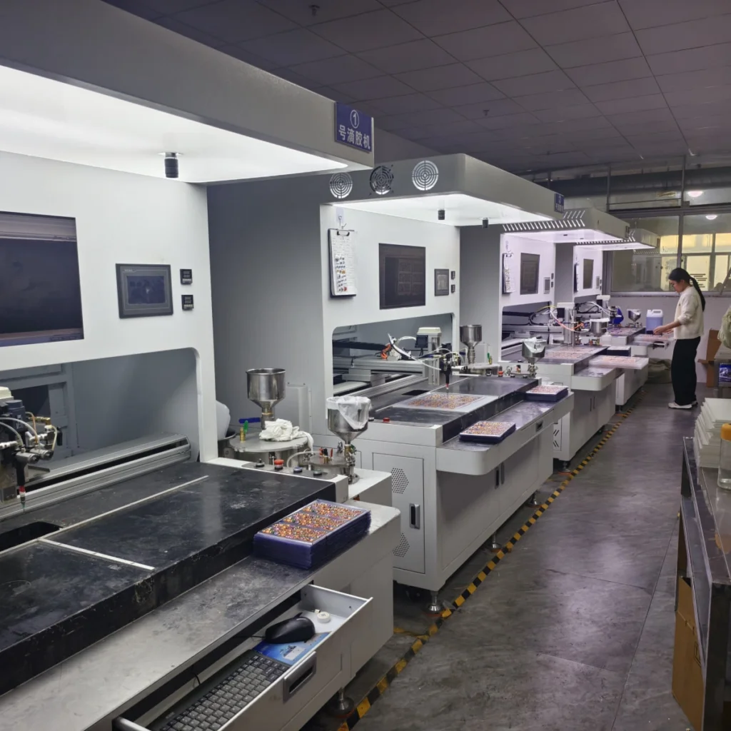
The same planning method can be adapted for domed decals, domed badges, domed nameplates, automotive emblems, or keychains. The fixture, resin qualification, cosmetic standard, and durability test must still match the actual product.
Start With a Product and Acceptance Profile
Group the expected orders into representative product families instead of specifying the line around one easy sample. Include the smallest resin area, largest target volume, most complex outline, most variable placement, and most demanding end-use condition. These cases define the practical operating envelope.
- Product geometry: overall dimensions, resin area, narrow sections, holes, cutouts, edge allowance, target dome height, and required volume.
- Layout: products per tray, row and column spacing, mixed orientations, print variation, free placement, and sheet or fixture datum.
- Construction: substrate, ink, coating, laminate, surface preparation, flatness, and any secondary cutting, forming, or assembly.
- Appearance: acceptable edge coverage, bubbles, cloudiness, tails, drips, surface marks, and approved visual reference.
- End use: indoor or outdoor exposure, flexibility, contact, chemical or cleaning exposure, temperature, UV, moisture, and required service tests.
- Production demand: order mix, changeover frequency, tray quantities, staffing assumption, scheduled time, accepted output, and allowed rework or scrap.
Surface energy, ink, coating, contamination, and product flatness can change resin wetting and adhesion. Confirm cleaning, priming, corona treatment, or other surface preparation only through a controlled adhesion and cure test on the final construction. For a sticker-focused purchasing path, use the sticker doming machine selection guide.
Choose the Positioning Method Before Comparing Automation
The most useful first question is not “How automatic should the line be?” It is “How repeatable is the real product position?” Positioning determines operator work, programming, fixture needs, and the risk of resin missing the intended boundary.
PJ180
Operator-controlled positioning
Best fit: samples, changing products, pilot work, smaller batches, or simple regular rows that an operator can index reliably.
Setup risk: operator rhythm, needle height, path control, and tray movement affect consistency and usable output.
DJ771
Saved paths on repeat coordinates
Best fit: regular sheets or rigid products that return accurately to a reference point or purpose-built fixture.
Setup risk: a correct program still misses the product if the next tray does not match the saved coordinates.
SJ4060
Vision-guided position recognition
Best fit: mixed layouts, holes, cutouts, free placement, or print variation that fixed coordinates cannot control reliably.
Setup risk: the real artwork, contrast, gloss, transparency, and recognition reference must be validated.
DJ771 can execute complex programmed paths; its limitation is repeat placement, not path complexity alone. Fixtures can therefore make it a cost-effective option for rigid badges, nameplates, automotive emblems, and keychains. SJ4060 becomes more valuable when the customer would otherwise spend time aligning every tray or accepting positioning-related rejects. On a simple regular sheet, vision does not guarantee a large increase in dispensing output.
A manual syringe or basic dispensing station can still support early experiments, repairs, and one-off work. It should not be treated as equivalent to controlled two-component metering when mix ratio, delivered volume, and repeatability are formal acceptance requirements. The semi-auto vs automatic doming machine guide provides a broader workflow comparison.
Decide Between Single-Head and Multi-Head Dispensing Separately
Head count is independent of the positioning platform. PJ180, DJ771, and SJ4060 can all be evaluated with a single needle or a compatible multi-head component.
- Use multiple heads only when the active positions share compatible spacing, path geometry, target volume, and resin behavior.
- Confirm that the selected pumps can supply the combined flow while controlling the smallest required shot.
- Measure outlet-to-outlet balance, start and stop behavior, alignment, priming, cleaning, and inspection work.
- For very small or precision-sensitive products, start with a small-pump, single-head sample test instead of relying on a universal size threshold.
Use Single-Head vs Multi-Head Resin Doming for the complete nozzle-spacing, flow-balance, small-shot, and validation decision.
Match the Resin, Pumps, Mixer, and Process Window
Resin chemistry does not select the machine by itself. Start with the exact product code and current technical data sheet, then record the properties that affect storage, metering, mixing, edge hold, cure, safety, and final performance. The doming resin selection center can help identify which epoxy or polyurethane formulation should be tested first.
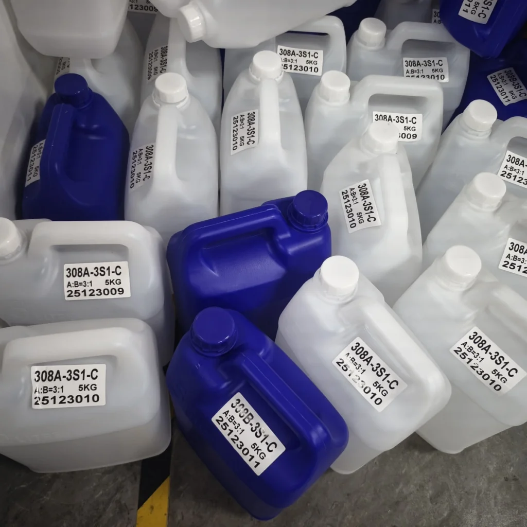
Component identity and mix-ratio basis
Record A and B product codes, lots, densities, and the specified ratio. A ratio by weight is not automatically the same as a ratio by volume. Because a gear-pump system meters displacement, the supplier must confirm how density and pump settings produce the resin manufacturer’s required ratio.
Viscosity and operating temperature
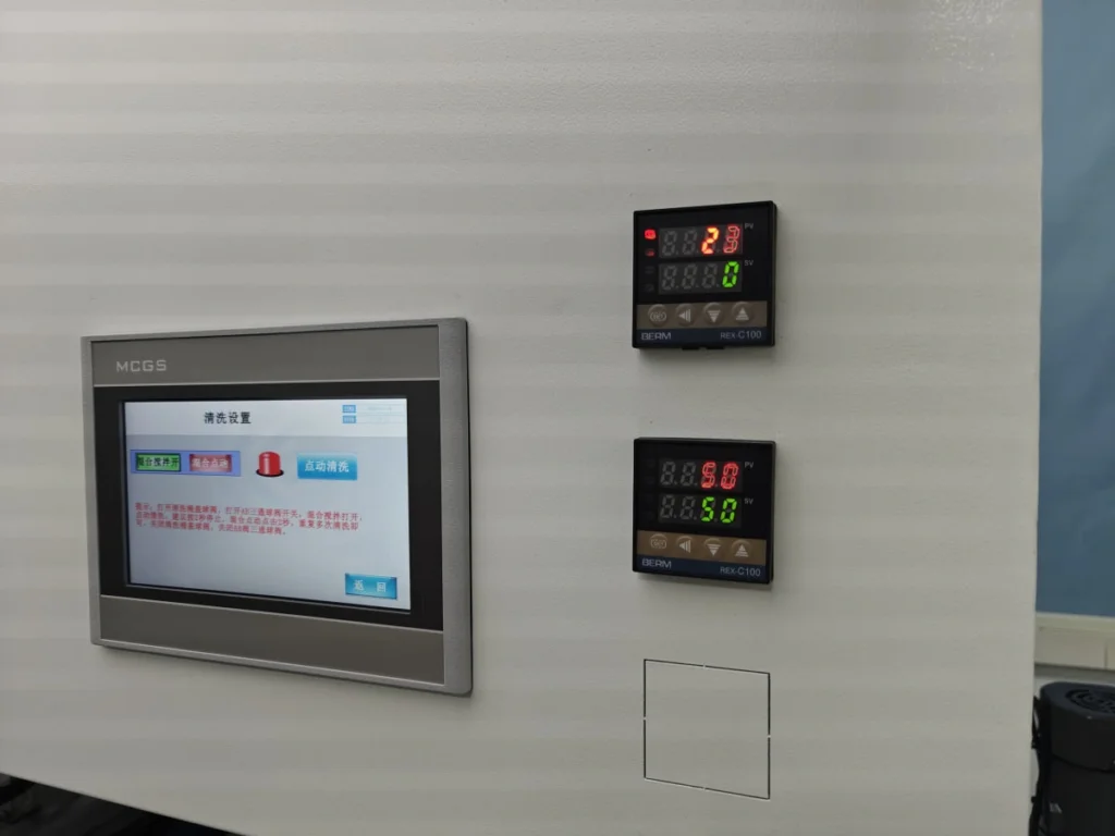
Use viscosity at the proposed operating condition, not an undefined “room temperature” value. Maintain the material and workshop within a window supported by the resin supplier and verified in testing. Tank, hose, or room temperature control should be added only when the formulation permits it and the trial confirms that it improves stable delivery without creating a new pot-life, reaction, or safety problem.
Degassing and moisture control
Do not specify vacuum degassing solely because the material is called polyurethane, and do not assume epoxy never needs it. Bubbles can come from stored air, mixing, leakage, hose or pump conditions, substrate geometry, moisture, or the chemical reaction. Confirm which component may be degassed, the vacuum procedure, allowable hold time, and moisture-control method from the resin documentation and sample result.
Pump displacement and minimum controllable shot
Each machine model can use different pump sizes, so there is no universal output range tied to the model name. Larger displacement can support higher resin demand but may provide less useful adjustment resolution for very small shots. Smaller pumps improve fine-volume control but can extend dispensing time for large products or multi-head flow. Select the candidate pumps from the actual resin ratio, volume range, viscosity, number of heads, and smallest acceptable shot, then verify them with repeated samples.
Mixing and suck-back
Dynamic and static mixing arrangements have different pressure, cleaning, maintenance, and consumable implications. Ask the supplier to identify the exact mixer, replaceable parts, cleaning method, and validated material range. Suck-back can help reduce dripping, but it does not guarantee a clean stop and must be tuned with the resin, hose, mixer, and needle because an excessive setting can disturb restart behavior or introduce air.
Plan Accepted Output and Curing Capacity Together
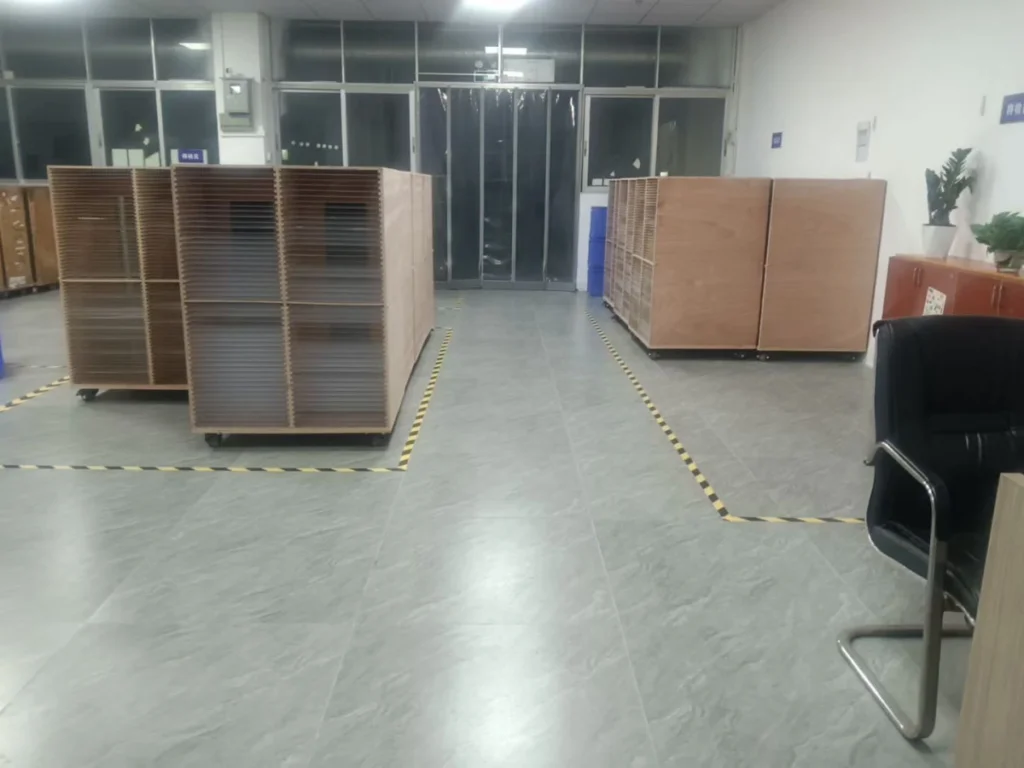
The line layout must connect the measured tray rhythm to curing, inspection, rework, and packing. Reserve level rack positions, safe aisles, transfer space, operators, and quarantine capacity for the actual product mix and verified cure stages.
This page uses accepted output only as a line-capacity input. Build the detailed estimate from the proposed pumps, head count, resin, tray, positioning method, loading sequence, interruptions, and measured yield in the resin doming production-output guide.
Confirm Utilities, Facility Conditions, and Safety Controls
Request a configuration-specific utility schedule before approving the layout. Gear pumps are motor-driven metering devices, so an external air supply should not be assumed from the word “pump.” Pneumatic valves, pressure-assisted material supply, vacuum systems, or other options may still require compressed air or vacuum.
| Facility item | Confirm before installation | Why it matters |
|---|---|---|
| Electrical supply | Voltage, phase, frequency, connected load, protective devices, grounding, plugs, and loads for heaters, vacuum equipment, or cure equipment | Prevents an incomplete installation or unsafe temporary wiring |
| Compressed air or vacuum | Whether the quoted configuration requires it; pressure or vacuum range, flow, air quality, filtration, drainage, and connection | Optional valves, pressure supply, or degassing functions may not work as specified without the correct service |
| Temperature and humidity | Storage, dispensing, and curing limits from the actual resin documentation; monitoring location and alarm or response method | Changes in material condition can alter viscosity, flow, bubbles, and curing behavior |
| Level surfaces and access | Machine foundation, worktable and tray flatness, rack level, aisle width, loading reach, service clearances, and safe material movement | Uncured domes can shift or overflow if trays tilt, and poor access increases handling and maintenance time |
| Cleanliness and lighting | Dust control, covered cure where required, inspection lighting, contamination sources, and cleaning responsibility | Dust and poor inspection conditions can reduce cosmetic yield or hide defects |
| Exposure and emergency controls | Current SDS for both components and cleaning materials; occupational-hygiene assessment; required enclosure, local exhaust or general ventilation; PPE; spill, first-aid, fire, and waste procedures | Risk controls depend on the actual formulation, cleaning task, quantity, temperature, and local regulation |
Safety boundary: low odor does not prove low hazard. Select engineering controls, gloves, eye or face protection, protective clothing, and waste handling for the actual A component, B component, cleaning material, and task. Isolate the machine and release stored pressure before opening any pressurized or wetted component according to the manufacturer’s procedure.
If conveyor transfer, automatic loading, upstream printing, or downstream cure automation is required, treat it as a separate engineering scope. Define tray interfaces, timing signals, buffer capacity, guarding, fault recovery, and responsibility for the complete integrated-line acceptance test.
Plan Consumables, Cleaning, and Maintenance by Fluid Zone
In a normal two-component system, the A and B materials remain separate through their storage, pumps, and supply paths and meet at the mixing stage. Short pot life mainly affects wetted parts after the mix point, such as the mixer, outlet, and needle. Do not describe every hose and pump as carrying mixed resin, and do not use a general solvent-flushing instruction for every component.
- List actual consumables: mixer or mixing elements, needles, seals, filters, hoses, valves, cleaning materials, and any configuration-specific wear parts.
- Separate procedures by state: startup, short pause, overnight stop, long shutdown, resin change, and restart can require different actions.
- Use approved cleaning materials: compatibility, exposure controls, fire risk, PPE, and waste disposal must be confirmed by the machine and material documentation.
- Keep the A and B circuits identifiable: prevent cross-contamination of tanks, tools, containers, pumps, and return paths.
- Define preventive maintenance: calibration, leakage checks, drive and pump inspection, mixer condition, hose condition, safety devices, filters, and software or recipe backup.
- Hold risk-based spares: identify parts whose failure would stop production and confirm lead time rather than buying a generic spare-parts kit.
- Record changes: resin lot, pump or mixer work, replaced parts, calibration, cleaning, abnormal stops, and corrective action should remain traceable to production results.
Decision Matrix: Match the Setup to the Constraint
| Dominant production condition | Configuration to evaluate first | What the sample test must prove |
|---|---|---|
| Changing samples, pilot work, or high product variety with manageable manual movement | PJ180 or an appropriate controlled manual setup | Operator repeatability, minimum and maximum shot, changeover, cleaning time, and accepted output |
| Regular sheets with repeat coordinates | DJ771 with a repeatable tray datum or fixture | Placement repeatability, saved path, complete tray cycle, and yield across representative trays |
| Mixed layouts, holes, cutouts, print shift, or free placement | SJ4060 after camera-recognition testing | Recognition reliability, permitted position variation, path correction, failure handling, and accepted yield |
| Rigid badges, nameplates, emblems, or keychains in repeat positions | DJ771 with a purpose-built fixture; compare SJ4060 only if fixture control is insufficient | Fixture loading time, coordinate repeatability, part flatness, edge hold, and complete cycle |
| Very small resin areas, approximately below 2–3 mm wide | Single head with suitably small-displacement pumps | Minimum stable volume, placement tolerance, dome quality, and rejected-piece rate |
| Regular repeated positions that support parallel dispensing | Compatible multi-head assembly on PJ180, DJ771, or SJ4060 | Needle spacing, outlet balance, combined flow, alignment, cleaning, complete cycle, and accepted yield |
PJ180 can be paired with compatible desktop or floor-standing 3-axis platforms when the resin unit, working area, hose routing, controls, and intended workflow are confirmed together. This is a specific configuration path, not proof that every semi-auto machine can be upgraded. Move toward saved-path automation when manual positioning becomes the measured bottleneck; evaluate vision when placement variation or precise tray loading creates the larger loss.
Use a One-Way Material and Product Flow
- Receive and quarantine materials. Verify A/B identity, lot, condition, documentation, and shelf life before release.
- Store and condition the resin. Keep components separated and bring them into the validated process window without undocumented heating or degassing.
- Prepare products and trays. Clean as required, confirm revision, load the fixture or sheet datum, and protect prepared parts from dust and mix-ups.
- Meter, mix, and dispense. Use the released recipe and record any intervention, adjustment, or rejected setup piece.
- Transfer trays level into curing. Avoid crossing dirty, unpacking, or rework traffic through the uncured-product route.
- Inspect at the specified cure stage. Separate early handling checks from full-cure, adhesion, or durability acceptance.
- Quarantine nonconforming output. Keep rework and scrap from re-entering accepted production without a documented decision.
- Pack and release traceably. Link finished batches to material lots, machine recipe, inspection results, and deviations.
Maintain safe service clearances and operator access instead of arranging machines only to maximise floor density. Buffers should protect the process from normal timing differences without hiding excessive work-in-process or extending resin residence beyond the validated cure plan.
Separate Sample Testing, FAT, and SAT
Use three distinct approval gates:
- Feasibility sample: confirms that a recorded product, resin, pump, head, positioning, and cure configuration can meet the agreed product criteria.
- Factory Acceptance Test (FAT): checks the ordered machine and contracted configuration before shipment.
- Site Acceptance Test (SAT): checks the installed process with site utilities, trained operators, material flow, curing, inspection, and records.
Carry the accepted configuration into the purchase specification so later tests do not become subjective demonstrations. The complete scope, evidence package, timing records, deviations, and retest rules belong in the Doming Machine Sample Test and Acceptance Checklist.
Common Production-Line Setup Mistakes
- Selecting from a fixed daily-output threshold. Pieces per shift change with volume, shape, head count, pumps, loading, cleaning, curing, and yield. Use a measured complete cycle.
- Assuming higher automation means higher dispensing output. On a simple regular sheet with comparable pumps and multi-head configuration, the main difference may be operator and positioning work.
- Buying the largest pump or most heads. Maximum flow can conflict with the minimum controllable shot and alignment tolerance.
- Using heating or degassing as a universal remedy. Both are process options that require formulation-specific approval and validation.
- Planning only the machine footprint. Material storage, tray staging, level transfer, curing racks, inspection, quarantine, maintenance access, and safe aisles consume real space.
- Treating every wetted component as one cleaning circuit. Separate A, B, and mixed-material zones and follow the machine-specific procedure.
- Accepting one attractive sample. Qualification needs representative worst cases, repeatability, raw data, defects, complete timing, and agreed decision rules.
- Leaving safety and waste planning until installation. Resin components and cleaning materials must be reviewed before ventilation, PPE, storage, spill, fire, and disposal controls are finalized.
Supplier RFQ Checklist
Send the same technical package to every supplier so that quotations can be compared on a common basis.
- Application and product family: decals, labels, badges, nameplates, emblems, keychains, or other products, including representative best and worst cases.
- Drawings and layout: dimensions, resin boundary, target dome profile, products per tray, spacing, orientation, holes, cutouts, and expected placement variation.
- Final construction: substrate, ink, coating, laminate, cleaning or treatment method, flatness, and secondary processing.
- Resin documentation: manufacturer, product codes, A/B lots if available, weight and volume ratio, density, viscosity, working time, cure schedule, storage limits, TDS, and SDS.
- Quality requirements: volume or profile, edge allowance, bubble and cosmetic limits, cure, adhesion, durability, sampling, accepted/rework/scrap definitions, and evidence format.
- Production model: order mix, changeovers, scheduled shifts, staffing, target accepted output, tray-change method, cleaning plan, and cure capacity.
- Candidate configuration: pump sizes, single or multi-head, mixer, needle, fixture or vision method, working area, resin conditioning, and cure approach.
- Facility data: electrical supply, available air or vacuum, room conditions, floor and aisle space, ventilation assessment, material storage, waste route, and local requirements.
- Documentation and support: manuals, drawings, utility schedule, consumables, spares, preventive maintenance, training, remote or on-site support, warranty, and response process.
- Acceptance plan: sample quantity, setup allowance, test protocol, FAT/SAT criteria, responsibilities, deviation approval, retest, and commercial response to failure.
FAQ
What is the most important factor when choosing a resin doming machine?
The most important first decision is how the real product will be positioned repeatedly. Regular fixed coordinates support saved-path 3-axis production, changing products may favor operator-controlled positioning, and variable placement may justify CCD vision. Pump and head configuration must then be selected from the resin volume and precision requirement.
How many pieces per day justify an automatic doming machine?
There is no universal threshold. Measure complete tray cycles and accepted yield with the proposed resin, pumps, heads, layout, loading, curing, inspection, and cleaning. Automation is justified when it removes a measured labor, positioning, consistency, or capacity constraint at the required product mix.
Can PJ180 be upgraded to automatic 3-axis production later?
PJ180 can be paired with compatible desktop or floor-standing 3-axis platforms, including configurations built around DJ331, DJ6331, or DJ771. Confirm the working area, mechanical and control compatibility, hose routing, fixture method, and quoted upgrade scope before purchase. This should not be generalised to every semi-auto machine.
Does every doming line require compressed air?
No. Confirm the exact quoted configuration. Pneumatic valves, pressure-assisted supply, or optional systems may require clean, dry compressed air, while the gear-pump metering itself is motor driven. The supplier should state pressure, flow, air-quality, and connection requirements.
Does polyurethane resin always require vacuum degassing?
No. Degassing depends on the formulation, component condition, moisture sensitivity, handling, mixing, equipment, and sample result. Some epoxy systems may also benefit from controlled degassing. Follow the resin supplier’s documented limits and validate the actual components rather than applying one rule by chemistry name.
How much curing-rack space is required?
Multiply the measured tray-entry rate by the verified time each tray must occupy the curing area, then add allowance for transfer, inspection timing, product mix, quarantine, safe aisles, and spare positions. Use the slowest approved cure schedule that the line must support, not only the fastest sample.
What makes a supplier sample test reliable?
The test should use real or approved representative products and material, identify the machine and full configuration, separate setup from qualification pieces, include worst-case products and repeated trays, record complete timing and rejects, and compare results with pre-agreed acceptance criteria. A short video or one attractive sample is not sufficient.
Final Setup Rule
Build the line from the product outward: define the accepted dome, qualify the resin and substrate, choose pumps and head count, select the positioning method, measure the complete tray cycle, size curing and inspection, then confirm utilities, safety, maintenance, and acceptance evidence.
This sequence prevents a fast machine from being installed inside a slow or unstable process. It also gives suppliers enough information to compare PJ180, DJ771, and SJ4060 configurations honestly, without converting automation level or an ideal cycle into a universal production promise.